Icom IC-756 Pro III
Primary fixed HF station with PC integration and WSJT-X digital operation.
Antennas · fixed stations · mobiles · handhelds · software
A station is a set of roles, not a shelf of radios. The antenna, feed line, power, grounding, software and propagation path decide whether a particular transceiver is useful at that moment.
Otherwise it is an expensive shelf ornament with a coax problem.
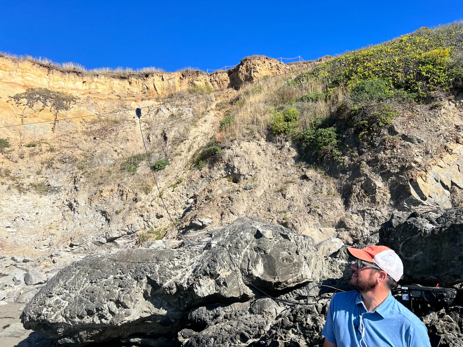
Station to field
The Home QTH and field station are parts of one operating system.
Antennas
| IC-756 Pro III switch · Mosley TA-32M beam | Two elements for 20, 15, and 10 meters at approximately 20 feet above ground. Directional HF work; fully DC grounded through its antenna and switched-feed arrangement. |
|---|---|
| IC-756 Pro III switch · 80-meter loop | The most-used HF antenna at the Home QTH. A 9:1 balun and window-line feedline serve the loop. It has a lightning arrestor and a grounded shunt that provide a static-drain path, but the loop is not fully DC grounded. |
| IC-756 Pro III switch · 40-meter dipole | Normally part of the switched HF antenna set and fully DC grounded through its switched-feed arrangement. Currently down for replacement. |
| Arrow 2m/70cm J-pole | Nominally portable, but installed on the Home QTH roof with something approaching tenure. It presently feeds the secondary FT-897D for VHF/UHF; a quick-connect arrangement is planned so the FT-5DR can use that same external antenna when wanted, one radio at a time. |
| Shack roll-up J-pole | Dedicated portable-style VHF/UHF J-pole kept in the shack for the FT-5DR. It gives the handheld a proper external antenna without having to borrow the roof feed line. |
| Workman III triple-collinear | QTH Kenwood TM-D700A VHF/UHF, APRS, packet, and local voice layer. |
Every fixed antenna path has a defined DC/static or bonding strategy, but those jobs are kept distinct. A DC path can bleed static; bonding and surge protection manage fault and lightning energy; common-mode control manages RF on the outside of feed lines. None of those phrases means “lightning proof,” and none is a magic cure for receiver noise.
Radios in rotation
Primary fixed HF station with PC integration and WSJT-X digital operation.
Secondary all-mode QTH station. HF when wanted; VHF/UHF through the roof-mounted Arrow J-pole. It is one of several places from which local VHF/UHF can be monitored or answered.
Compact all-mode HF/VHF/UHF utility where a smaller station role is useful.
The QTH unit runs on the Workman III triple-collinear. The TM-D700A family remains especially useful because its APRS implementation still supports classic 100 Hz Voice Alert behavior.
A durable 2-meter FM radio available with the smaller Workman II vertical for local fixed-station work.
One of the primary portable/field radios for analog FM, C4FM, APRS, travel, hotspot access, and field use. At the shack it has a dedicated roll-up J-pole; a planned quick-connect will also let it use the roof-mounted Arrow J-pole when the FT-897D is disconnected from that feed.
BTECH and other appropriately programmed handhelds support lawful family coordination and backup roles.
GEARS at 147.975 MHz (-600 kHz), PL 110.9 Hz is a standing local watch channel across the station and mobile operating plan. The FT-2400 provides a dedicated 50-watt fixed-station response path, while other fixed and mobile radios can take the same role when appropriate. “Usually monitoring 146.850- PL 110.9” describes the operating plan, not a promise about which radio, room, vehicle, or operator location is active at any moment.
Software and linked systems
A DC path can bleed accumulated static and place connected conductors at a common potential. That is different from an effective RF return path, protective electrical bonding or a complete lightning-protection system. A DC-grounded antenna, a coax switch or a surge protector alone does not make the station lightning-proof.
At this station, the beam and switched dipole paths have documented DC-grounding arrangements. The 80-meter loop’s arrestor and static-drain arrangement should not be described as a fully DC-grounded antenna. Maintain the actual bonding and entry protection as a coordinated installation; do not add an isolated ground rod as a substitute for proper bonding.
A transmission-line stub is a length of line terminated open or shorted. Its impedance at the connection changes with electrical length and frequency. A shorted quarter-wave stub can present high impedance at its design frequency while providing a DC path, but it is not a universal surge solution. Other lengths can act as matching or filtering elements. Cable velocity factor, connectors and operating band matter; “shorting stub” is not a interchangeable name for any piece of coax.
Balanced window line can be useful for a multiband antenna because it can have modest losses even with substantial standing waves, provided it is installed and matched properly. The loop’s 9:1 device is part of this particular matching arrangement. A 9:1 impedance ratio is a nominal transformation, not proof that an antenna is always 450 ohms or that every tuner wants that ratio. Feed-point impedance changes with frequency and line length; common-mode suppression and transformer heating must also be considered.
For local VHF/UHF, elevation and clearance often improve the radio horizon and reduce obstructions. On HF, height in wavelengths changes the radiation pattern: low horizontal antennas may favor regional high-angle paths, while greater height can support lower-angle paths useful for distance. “Higher” and “better” need a specified contact goal.
Study reference: ARRL grounding resources. For station work, use the equipment manuals and applicable installation requirements with competent local help.
| Radio | Useful distinction | Boundary |
|---|---|---|
| UV-5R Mini | Compact dual-band 2 m / 70 cm analog FM handheld. | Check the exact Mini manual and battery/accessory fit. |
| BTECH UV-5X3 | Analog FM adds the 1.25 m / 220 MHz amateur band. | Needs an antenna suitable for the selected band. |
| FT-5DR | Native C4FM plus analog FM; the OS4P handles supported cross-modes. | Not a native DMR, P25, NXDN or M17 handheld. |
Neither Baofeng/BTECH model supplies C4FM. Amateur handhelds do not replace certified GMRS/FRS equipment or the required operator license. Sources: Baofeng manuals, BTECH UV-5X3.
Station engineering
A radio station is an RF system sitting inside an electrical system, connected to antennas outdoors, computers indoors, power wiring everywhere, and a planet that occasionally throws lightning at it. “Ground it better” is not an engineering diagnosis. Electrical safety grounding, lightning protection, bonding, antenna counterpoise/radial systems, and common-mode RF control are different jobs. They overlap, but treating them as one mystical ground wire is how perfectly tidy installations become very effective antennas in places nobody intended.
The station uses short, low-impedance bonds between equipment and a defined entry/bonding point for conductors entering the building. Any station grounding electrodes must be bonded to the building grounding-electrode system in accordance with applicable electrical rules. An isolated “radio ground” rod is not an independent universe. During a fault or surge, separated grounds can create exactly the voltage difference the operator was hoping to avoid.
In ideal coax, the desired RF current on the center conductor is balanced by the return current on the inside surface of the shield. Common-mode current on the outside of the shield does not cancel. The feed line then radiates and receives. That can drag RF into the shack, distort the antenna pattern, change the apparent tuning when the cable moves, and carry household noise toward the antenna. A low SWR does not prove common-mode current is absent.
The practical cure is to interrupt the unwanted current path with a properly designed common-mode choke/current balun, appropriate bonding, and sane cable routing. Ferrite mix, number of turns, cable geometry, power and frequency matter. Unknown clamp-on ferrite is a thing, not a specification. K9YC and W1HIS both make the same larger point from different directions: common-mode impedance has to be substantial over the frequencies that matter, and the choke belongs where it actually breaks the unwanted path.
Transmission line has characteristic impedance, velocity factor, conductor and dielectric loss, shielding characteristics, power limits, weather limitations and an electrical length. Velocity factor matters whenever the line is being cut to an electrical length. Loss rises with frequency and length. Mismatch adds more loss. A suspiciously pretty SWR at the transmitter can be a lossy feed line hiding an ugly antenna load, which is the radio equivalent of solving a smoke alarm by removing the battery.
For ordinary HF runs, conductor size and shield resistance matter greatly. At VHF/UHF, feed-line loss becomes even more expensive. Weatherproof outdoor connectors, provide mechanical strain relief, avoid tight bends, and measure from the antenna end when diagnosing something important. The feed line is part of the station and deserves the same suspicion as the radio.
Open and shorted transmission-line sections transform impedance in predictable ways. Properly cut and measured, they can create deep notches at unwanted frequencies, suppress harmonics, and increase isolation between nearby transmitters and receivers. Their length depends on the operating frequency and the actual velocity factor of the cable; real cable loss limits the depth of the null. That is why a stub copied from somebody else's station is a starting dimension, not a finished component. Cut long, measure, trim, and verify with an analyzer or VNA.
The W2VJN material on interstation interference is particularly useful because it forces the right question: how much unwanted transmitter energy reaches the other receiver, and what can that receiver tolerate before blocking, intermodulation, noise or damage occurs? Antenna separation helps, but filters, stubs, band choice, physical layout and power management may all be required in a multi-radio station.
No arrestor makes a direct strike courteous. The objective is to keep conductors bonded, route surge current away from equipment, use appropriate protective devices, and make the station's disconnect plan realistic. DC-grounded antennas can provide a static-drain path. Quarter-wave shorted stubs can present useful RF and low-frequency/static behavior in specific designs. Neither replaces code-compliant bonding and surge protection. A clever RF trick is still an RF trick, not a waiver from physics or the electrical code.
The FCC's current rules no longer give amateur stations a blanket service-specific exemption from routine RF-exposure evaluation. A station either falls within the current exemption criteria or it must be evaluated. Frequency, power, duty cycle, antenna gain and pattern, distance, ground reflection, and accessible areas all matter. The current ARRL calculator is a useful screening/evaluation tool, but the station configuration and actual operating duty cycle still have to be represented honestly.
Keep the current paths controlled. Bond equipment appropriately. Keep common-mode current out of the shack. Use current chokes/baluns where the antenna system calls for them. Protect and weatherproof outdoor connections. Give coax mechanical strain relief. Treat every new amplifier, computer, charger, Ethernet cable, USB cable, switching supply, antenna switch and wall wart as a possible new RF path until proven otherwise. Fix the path instead of merely turning the microphone gain down until the symptom becomes less humiliating.
| Symptom | First question | Likely direction |
|---|---|---|
| RF in audio or controls | Does it change by band, power, or cable position? | Common-mode choke, bonding, shield integrity, cable routing. |
| High receiver noise | Does it vanish when house circuits are killed? | Locate the source; choke/filter source cables; improve common-mode isolation. |
| Good SWR, poor performance | What is the feed-line loss and what does the antenna look like at the feed point? | Measure at the antenna; inspect connectors, water ingress and loss. |
| Two radios interfere | Is it harmonic, broadband noise, overload or intermodulation? | Increase isolation; add filters/stubs; change antennas or coordinate operation. |
| Static/storm concern | Where will surge current actually flow? | Bonding, entry protection, listed surge devices and a real disconnect plan. |
The working technical basis here comes from ARRL grounding/RFI guidance, Jim Brown K9YC's RFI and common-mode work, W1HIS on common-mode chokes, W2VJN on interstation interference and coaxial stubs, standard transmission-line theory, and current FCC RF-exposure rules. Older material is useful where the physics remains useful; it does not outrank current electrical or FCC requirements.